
 English


Varukorg
Din varukorg är tom, men det behöver den inte vara.
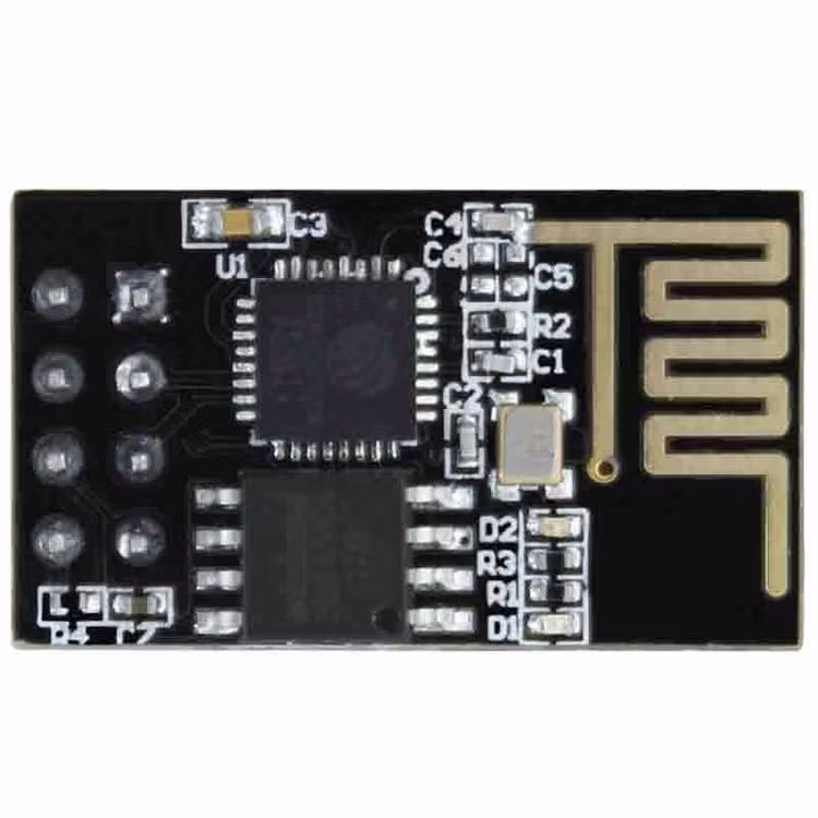
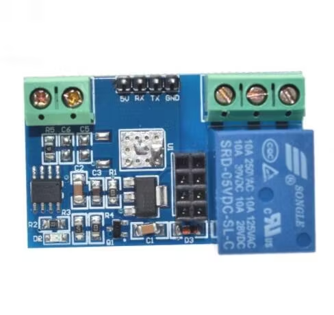
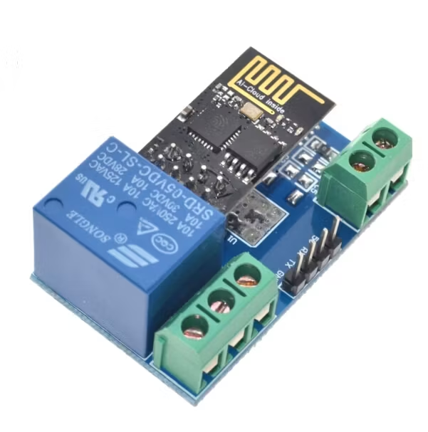
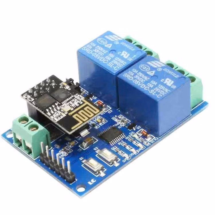
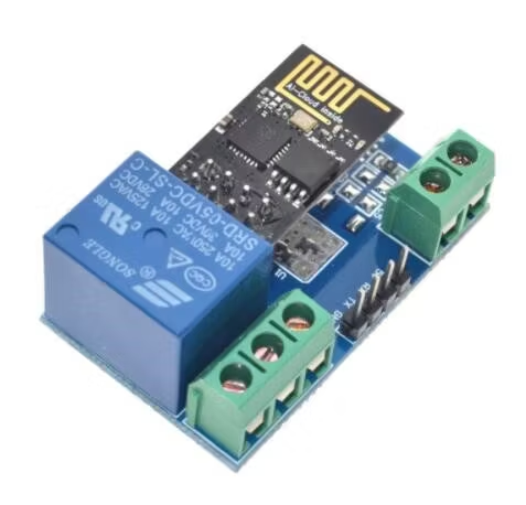
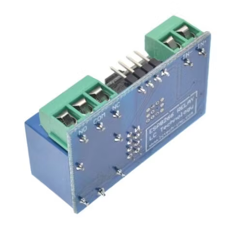
The 5VESP8266 dual-channel WIFI relay module uses ESP-01 as the WIFI module. With the mature and stable 8-bit MCU chip, the wireless control of the 2-way relay in the LAN using the mobile APP can be realized with a simple configuration process.
Function
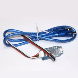
Onboard high-performance microprocessor and ESP-01WIFl module has two working modes: Mode 1: The mobile phone is directly mounted on the WIFI module mode 2: The mobile phone and the WIFI module are simultaneously mounted on the router. Additional functions: can also be used as a USB relay when the ESP-01 is unplugged. Transmission distance:(1) In the open environment, the maximum stable transmission distance of the mobile phone when it is mounted on the WIFI module is 100m;(2) When the WIFI module and the mobile phone are simultaneously mounted on the router, the transmission distance depends on the signal strength of the router. Use the Smartconfig technology to complete the configuration of the ESP-01WIFI module account and password on the mobile app. The configured account and password have the power-off memory function. Onboard 12V, 10A/250VAC10/30VDC relays, can be continuously sucked 100,000 times, with diode effluent protection and short response time. Onboard mode selection and real-time status indicatorReserved UART debug interface and chip program download interface board size: 59*40mm.
| Interface description | |
| IN+, IN- | 5V power input |
| TX, RX | UART serial port pins |
| 5V, GND, SWIM, NRST | STM8S microcontroller program download port |
| LED D2 and D4 | relay work indicator, lit when turned on (red light) |
| Press S1 | mode to switch, the default is mode 1 |
| Button S2 | Restore factory settings |
| LED D7 (red light) | mode 1 indicator |
| LEDD5 (blue light) | mode 2 indicator |
The working status indicator is described as follows:
(1) When it is extinguished, it means that it is self-configuring or losing connection with the router;
(2) When the 0.5S flashes, it means waiting for the mobile phone APP to configure the WIFI account and password for the ESP-01 module;
(3) When the 2S slow flashes, the configuration is completed, waiting for a TCP connection with the mobile phone;
(4) When it is always on, it means that the TCP connection is established successfully with the mobile phone.
2 jumper caps reserved
Please insert it into the bottom of normal use (ie RX connected to RX1, TX to TX1), if you want to use the USB to TTL serial
module to debug ESP-01 module, please plug it into the top (otherwise there may be interference)
COM1 public
COM2 public
NO1: Normally open, the relay is closed before the air is closed, and after the pull-in, it is short-circuited with COM1.
NO2: Normally open end, the relay is closed before the suction, and it is short-circuited with COM2 after the suction.
NC1: Normally closed-end, shorted to COM1 before the relay is pulled in, and suspended after suction
NC2: Normally closed end, the relay is shorted to COM2 before the suction is closed, and it is suspended after being sucked.
Relay control instruction (hexadecimal HEX format)
Open the first relay: A00101A2
Turn off the first relay: A00100A1
Open the second relay: A00201A3
Turn off the second relay: A00200A2

Din varukorg är tom, men det behöver den inte vara.