
 English


Varukorg
Din varukorg är tom, men det behöver den inte vara.
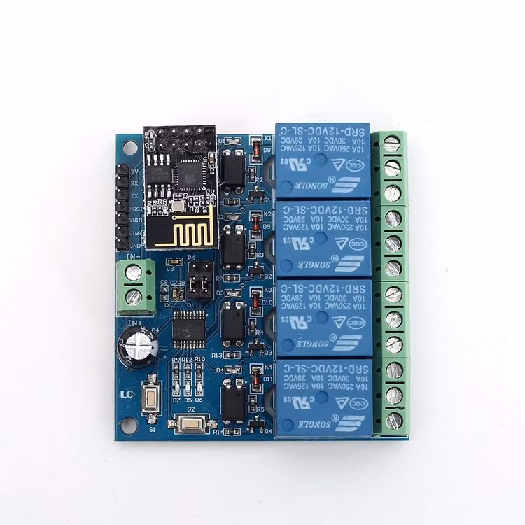
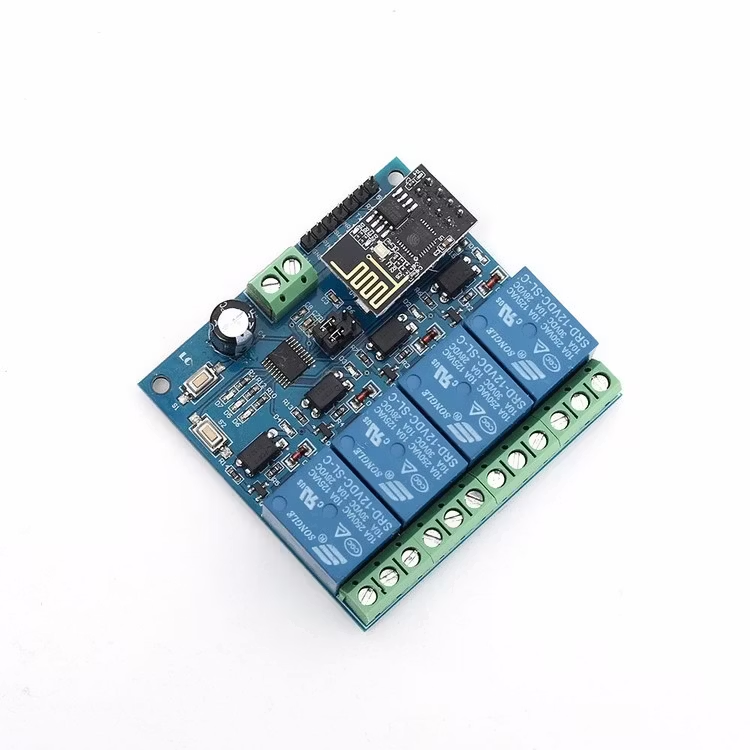
ESP8266 WIFI 4-Channel Relay Module is 4 channel WIFI relay module carried a ESP8266 WIFI module and mature 8 bit MCU, with Professional switching power supply circuit.It could control the relay by Android phone APP within the local area network (LAN).It is easy to set .
2.Features:
1 Integrated design.
2 APP remote control.
3 DC 12V work power supply.
4 Onboard high-quality MCU and ESP8266 WIFI module.
5 Support Two Work Mode:
Mode 1:cellphone carry on WIFI module directly.
Mode 2: cellphone and WIFI module carry on router together.
Additional features: USB Relay Module(Without ESP8266).
6 Transmission distance:
In the open environment, when the mobile phone is carrying on the WIFI module, the maximum transmission distance is 100 meter.
When the WIFI module and cell phone carrying on the router at the same time the signal transmission distance depends on the router signal.
7 Use the Smartconfig technology to complete the configuration of the account and password of the ESP8266 WIFI module on the mobile APP. The configured account and password will be memorized after power off.
8 Optocoupler isolated output, safe and reliable.
9 The board contains 220V,10A/250V AC 10A/30V DC Songle original relay, which can continuously absorb 100,000 times, with the protection of diode current and short response time.
10 PCB material and manufacturing process meets the standards of RoHS.
11 Onboard relay LED indicator, mode option and working statue LED indicator.
12 Reserved UART debug interface and MCU download port for the program.
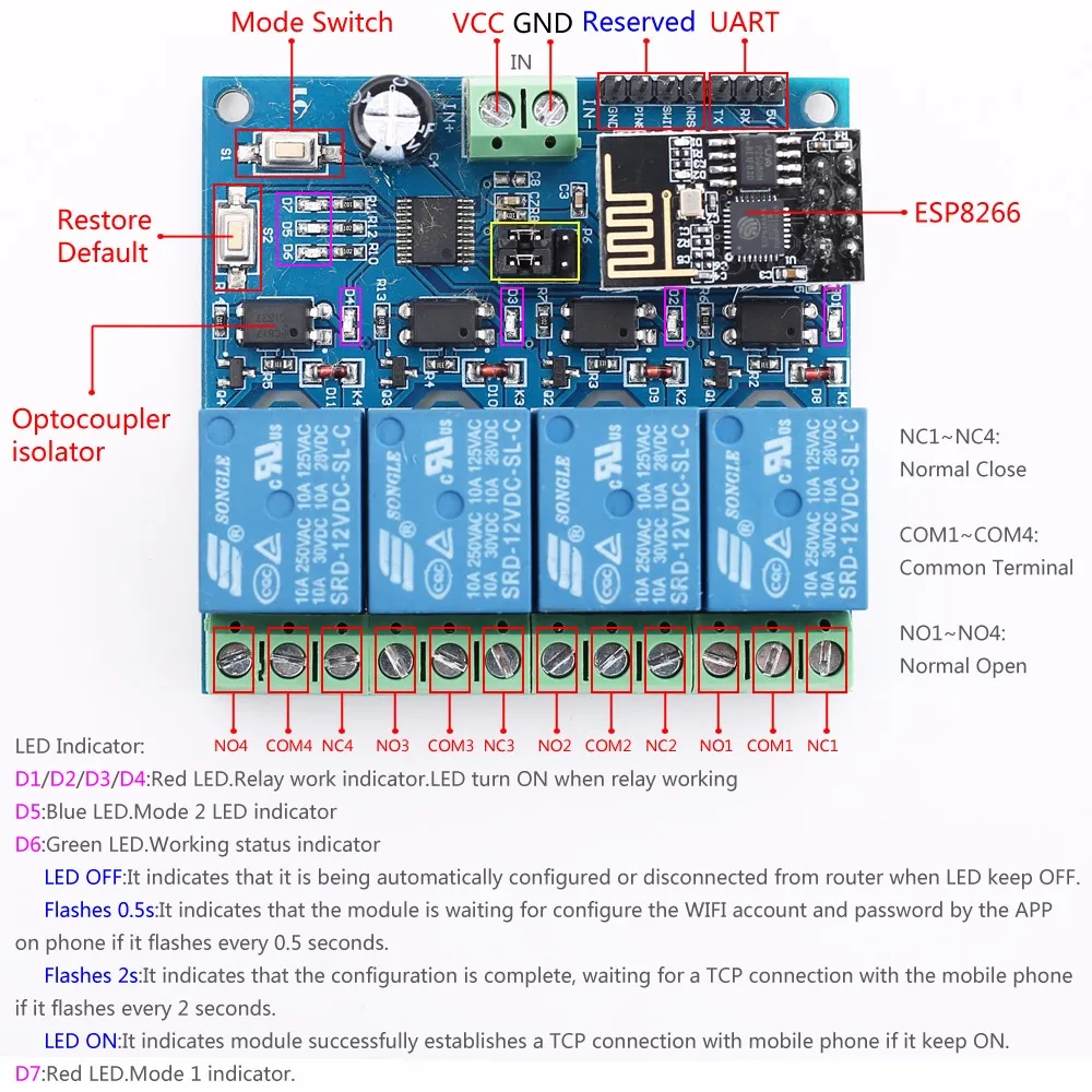
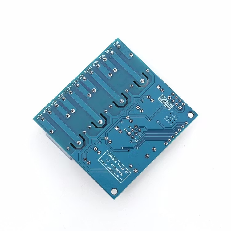
Port Description:
1 IN+:Power positive.Work voltage input terminal
2 IN-:Power negative.Work voltage input terminal
3 5V/RX/TX/GND:UART communication interface
4 NRST/PIN8/SWIN/GND:Code download interface for control IC by manufacturer.
5 S1 Button:It is used to switch work mode(default mode 1)
6 S2 Button:Restore factory settings.
7 D1~D4:Red LED.Relay work indicator.LED turn ON when relay working.
8 D5:Blue LED.Mode 2 LED indicator.
9 D6: Green LED.Working status indicator.
9.1 LED OFF: It indicates that it is being automatically configured or disconnected from the router when LED keep OFF.
9.2 Flashes 0.5s: It indicates that the module is waiting for configuring the WIFI account and password by the APP on the phone if it flashes every 0.5 seconds.
9.3 Flashes 2s: It indicates that the configuration is complete, waiting for a TCP connection with the mobile phone if it flashes every 2 seconds.
9.4 LED ON It indicates the module successfully establishes a TCP connection with the mobile phone if it keeps ON.
10 D7: Red LED.Mode 1 indicator.
11 Jumper Cap:
11.1 Install Jumper Cap: Default working status. It means module work in normal status.
11.2 Remove Jumper Cap: Test ESP8266 module separately by USB to TTL converter(Not recommended).
12 COM1~COM4: Common port from the relay.
13 NC1~NC4: Normal Close. It connects to COM by default status. Hanging when relay working
14 NO1~NO4: Normal Open. It disconnects to COM by default. Connect to COM when relay work.
15 Relay control command(Hexadecimal):
Turn OFF the first relay: A0 01 00 A1
Turn ON the first relay: A0 01 01 A2
Turn OFF the second relay: A0 02 00 A2
Turn ON the second relay: A0 02 01 A3
Turn OFF the third relay: A0 03 00 A3
Turn ON the third relay: A0 03 01 A4
Turn OFF the fourth relay: A0 04 00 A4
Turn ON the fourth relay: A0 04 01 A5
Configuration method:
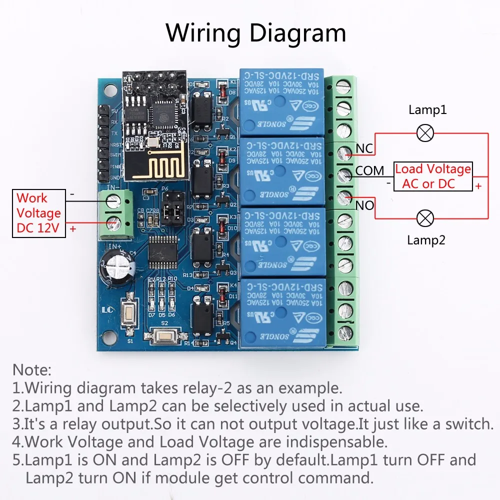
1 Connect DC 12V power supply at input terminal ‘IN+’ and ‘IN-’ which has marked on PCB.
2 Install APP ‘EspTouch_Demo’ on Android phone. User needs to configuration WIFI account number and password by MODE 2 at the first time to use it.
3 Install TCP transport tool APP ‘EasyTCP_20’ on Android phone.It is used to send the relay control command, click ‘SWITCH’, and then press the gray square in the interface to input the name and content of the relay control command respectively (the command format is HEX).
Work Mode 1(Phone carry on WIFI module directly):
1 It means that the configuration is complete if the green LED flashes cycle from 4 seconds slow down to 2 seconds after power-on;
2 The module sends an AP WIFI hotspot signal, which can be viewed in the WIFI network of the mobile phone, and then select the network.
3 Open APP 'EasyTCP_20',click 'CONNECT',input IP address:192.168.4.1 and port number 8080.And then click 'Connect'.Green LED flashes cycle from 2 seconds to keep ON after the connection is successful.Click on the grey square to send an instruction to control the relay's switch.
Work Mode 2(Phone and WIFI module carry on router together):
1 Short press S1 button to switch work mode to MODE 2 when the green LED flashes cycle from 4 seconds slow down to 2 seconds after power on. And then the blue LED turn ON. Green LED flashes cycle from 2 seconds faster to 0.5 seconds. It means that ESP8266 is waiting for the "EspTouch_Demo" APP to configure WIFI account number and password.
2 Open APP ‘EspTouch_Demo’ and input router password and then click ‘Confirm’.
3 Wait for the configuration to succeed. When the IP address of the ESP8266 (such as 192.168.0.174) appears on the APP interface.It means that the ESP8266 module is successfully connected to the router, and the account and password are automatically remembered. The next time when user enter mode 2, it will automatically connect (about 20-60 second);
Note:’192.168.0.174’ This IP address is dynamically assigned to the ESP8266 module by the router. The address may change after the next re-connection. User can view the real-time IP address of the ESP8266 module in the device list of the router.
4 Open the "EasyTCP_20" APP, click "CONNECT", enter the IP address of the ESP8266 module: 192.168.0.174 and port number 8080, and then click "Connect". After the connection is successful, the green flashing from 2 seconds to keep ON. Click on the grey square to send an instruction to control the relay's switch.
Additional features(Used as USB Relay):
1 Remove ESP8266 module.
2 Prepare a USB to TTL converter by yourself and connect it to the module.
3 Select Mode 1 and open UART debugging software such as SSCOM32 after green LED flashing by each 2 seconds.
4 Set Baud rate at 115200. Send control command in Hexadecimal to control relay.
9.Note:
1 For the first time, it will take a little longer (about 1 minute) to configure the WIFI password. After the configuration is completed, it will take 20 seconds to automatically connect at the next boot.
2 If a user wants to change the router, user can reset or press the S2 button(the WIFI account and password of the previous memory will be cleared by press the S2 button), and the WIFI account and password will be configured for esp8266 in mode 2.
3 When ESP8266 memory router signal is very weak or not in service area lead to the suspension of connection, the green light will go out and try to connect automatically, buttons are invalid state in the process when the green light is a change to 2-second slow flash which means it has returned to the connection.
4 The button can be used when the green light is 2 seconds slow flash or keep on at Mode 1 and mode 2, and the rest is self-configuring in the chip or waiting for the configuration process, and the button is invalid.
5 The mobile phone and esp8266 will automatically disconnect the TCP connection if there is no data communication for more than 6 minutes. And then click "CONNECT" in the upper right corner of "EasyTCP 20" APP to re-establish the connection.
6 It's relay output. So it can not output voltage. It just like a switch. Work voltage and load voltage are indispensable.
7 Please read the user manual and description before use.
Application:
1 Smart home control.Remote control of household appliances such as air conditioning, electric fans, rice cookers, lights, etc.
2 Automatic motor control
3 Production workshop intelligent operation
4 Intelligent farming control
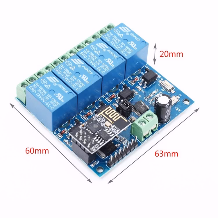
| Working Voltage | DC 12V |
| Load Voltage | DC 30V 10A /AC 250V 10A |
| Work Humidity | 0%~95%RH |
| Size | 63*60*20mm |


Din varukorg är tom, men det behöver den inte vara.