
 English


Varukorg
Din varukorg är tom, men det behöver den inte vara.
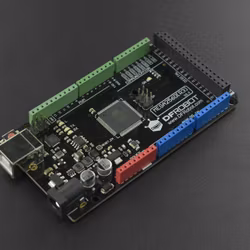
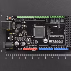
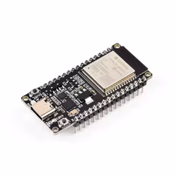
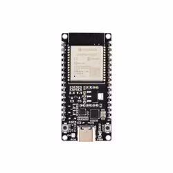
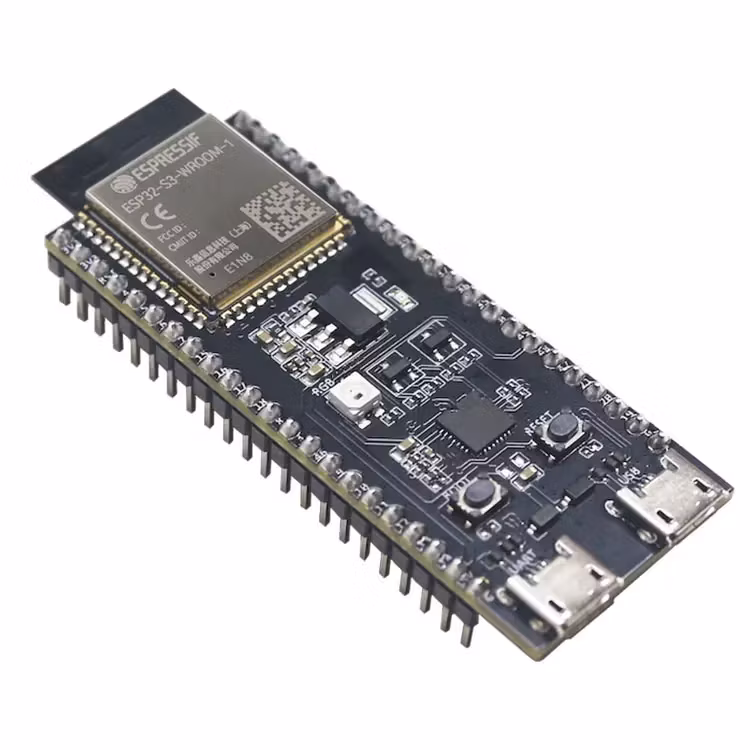
The ESP32-S3-DevKitC-1 is an entry-level development board equipped with ESP32-S3-WROOM-1, ESP32-S3-WROOM-1U, or ESP32-S3-WROOM-2, a general-purpose Wi-Fi + Bluetooth® LE MCU module that integrates complete Wi-Fi and Bluetooth LE functions.
Most of the I/O pins on the module are broken out to the pin headers on both sides of this board for easy interfacing. Developers can either connect peripherals with jumper wires or mount ESP32-S3-DevKitC-1 on a breadboard.

More you find here
| Key Component | Description |
|---|---|
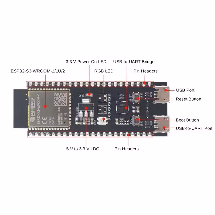
| ESP32-S3-WROOM-1/1U/2 | ESP32-S3-WROOM-1, ESP32-S3-WROOM-1U, and ESP32-S3-WROOM-2 are powerful, generic Wi-Fi + Bluetooth LE MCU modules that have a rich set of peripherals. They provide acceleration for neural network computing and signal processing workloads. ESP32-S3-WROOM-1 and ESP32-S3-WROOM-2 comes with a PCB antenna. ESP32-S3-WROOM-1U comes with an external antenna connector. |
| 5 V to 3.3 V LDO | Power regulator that converts a 5 V supply into a 3.3 V output. |
| Pin Headers | All available GPIO pins (except for the SPI bus for flash) are broken out to the pin headers on the board for easy interfacing and programming. For details, please see Header Block. |
| USB-to-UART Port | A Micro-USB port used for power supply to the board, for flashing applications to the chip, as well as for communication with the chip via the on-board USB-to-UART bridge. |
| Boot Button | Download button. Holding down Boot and then pressing Reset initiates Firmware Download mode for downloading firmware through the serial port. |
| Reset Button | Press this button to restart the system. |
| USB Port | ESP32-S3 full-speed USB OTG interface, compliant with the USB 1.1 specification. The interface is used for power supply to the board, for flashing applications to the chip, for communication with the chip using USB 1.1 protocols, as well as for JTAG debugging. |
| USB-to-UART Bridge | Single USB-to-UART bridge chip provides transfer rates up to 3 Mbps. |
| RGB LED | Addressable RGB LED, driven by GPIO38. |
| 3.3 V Power On LED | Turns on when the USB power is connected to the board. |
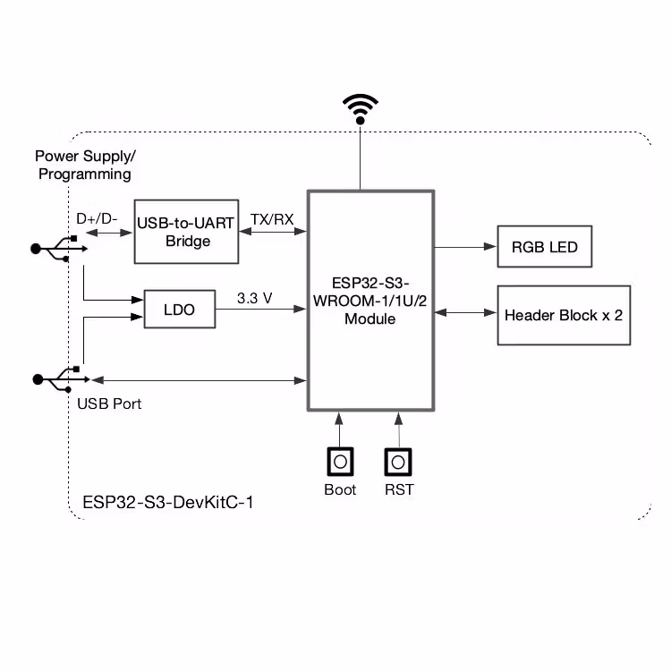
There are three mutually exclusive ways to provide power to the board:
USB-to-UART Port and ESP32-S3 USB Port (either one or both), default power supply (recommended)
5V and G (GND) pins
3V3 and G (GND) pins
Din varukorg är tom, men det behöver den inte vara.