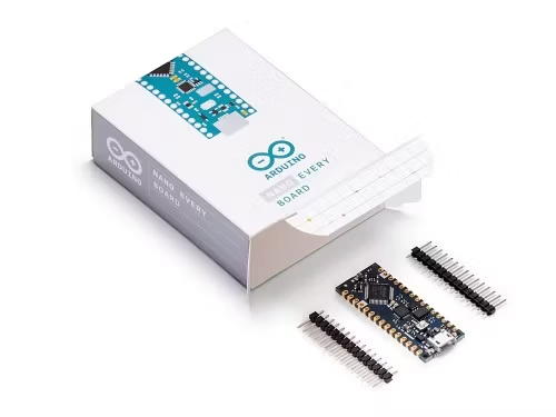
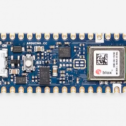
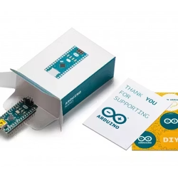
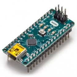
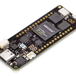
Förvandla dina idéer till en verklighet snabbt med den nya Arduino Nano Every.
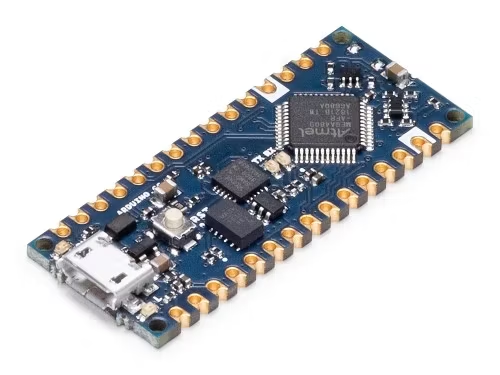
This small, robust and powerful board has the same classic Nano footprint loved worldwide.
It can be programmed with the easy to use Arduino IDE available offline and online. Get started in minutes with thousands of sketches available in open-source or write your own: it is the perfect choice for your everyday projects.
Based on the ATMega4809 AVR processor, the Arduino Nano Every is flexible to the requirements of your design. It can be used in a breadboard when mounting pin headers, or as a SMT directly soldered on a PCB thanks to its castellated pads. An SAMD11 ARM Cortex M0+ processor acts as a high performance USB to serial converter that can be re-programmed by skilled users to expand further the applications of this board.
Getting Started
In the Getting Started section, you can find all the information you need to configure your board, use the Arduino Software (IDE), and start to tinker with coding and electronics.
Do you want to learn more? Don’t miss the interview with Dario Pennisi, Arduino hardware and firmware development manager, who led the development of this board.
This board is based on the ATMega4809 microcontroller.
| Clock | 20MHz |
| Flash | 48KB |
| SRAM | 6KB |
| EEPROM | 256byte |
A ATSAMD11D14A Processor takes care of the USB to SERIAL communication and it is connected to the following pins of the ATMega4809 microcontroller.
| ATMega4809 Pin | ATMega4809 Acronym | SAMD11 Pin | SAMD11 Acronym | Description |
| 9 | PB05 | 15 | PA22 | SAMD11 TX -> ATMega4809 RX |
| 8 | PB04 | 16 | PA23 | ATMega4809 TX -> SAMD11 RX |
| 41 | UPDI | 12 11 | PA15 PA14 | UPDI RX UPDI TX |
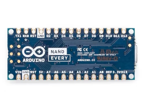
The board has a two 15 pins connectors - one on each side -, pin to pin compatible with the original Arduino Nano.
| Pin | Funcion | Type | Description |
| 1 | D13 | Digital | SPI SCK, GPIO |
| 2 | +3V3 | Power Out | Internally generated power output to external devices |
| 3 | AREF | Analog | Analog Reference; can be used as GPIO |
| 4 | A0/DAC0 | Analog | ADC in/DAC out; can be used as GPIO |
| 5 | A1 | Analog | ADC in; can be used as GPIO |
| 6 | A2 | Analog | ADC in; can be used as GPIO |
| 7 | A3 | Analog | ADC in; can be used as GPIO |
| 8 | A4/SDA | Analog | ADC in; I2C SDA; Can be used as GPIO |
| 9 | A5/SCL | Analog | ADC in; I2C SCL; Can be used as GPIO |
| 10 | A6 | Analog | ADC in; can be used as GPIO |
| 11 | A7 | Analog | ADC in; can be used as GPIO |
| 12 | +5V | Power Out | Internally generated power output to external devices |
| 13 | RST | Digital In | Active low reset input (duplicate of pin 18) |
| 14 | GND | Power | Power Ground |
| 15 | VIN | Power In | Vin Power input |
| 16 | TX | Digital | USART TX; can be used as GPIO |
| 17 | RX | Digital | USART RX; can be used as GPIO |
| 18 | RST | Digital | Active low reset input (duplicate of pin 13) |
| 19 | GND | Power | Power Ground |
| 20 | D2 | Digital | GPIO |
| 21 | D3/PWM | Digital | GPIO; can be used as PWM |
| 22 | D4 | Digital | GPIO |
| 23 | D5/PWM | Digital | GPIO; can be used as PWM |
| 24 | D6/PWM | Digital | GPIO; can be used as PWM |
| 25 | D7 | Digital | GPIO |
| 26 | D8 | Digital | GPIO |
| 27 | D9/PWM | Digital | GPIO; can be used as PWM |
| 28 | D10/PWM | Digital | GPIO; can be used as PWM |
| 29 | D11/MOSI | Digital | SPI MOSI; can be used as GPIO |
| 30 | D12/MISO | Digital | SPI MISO; can be used as GPIO |

 Svenska
